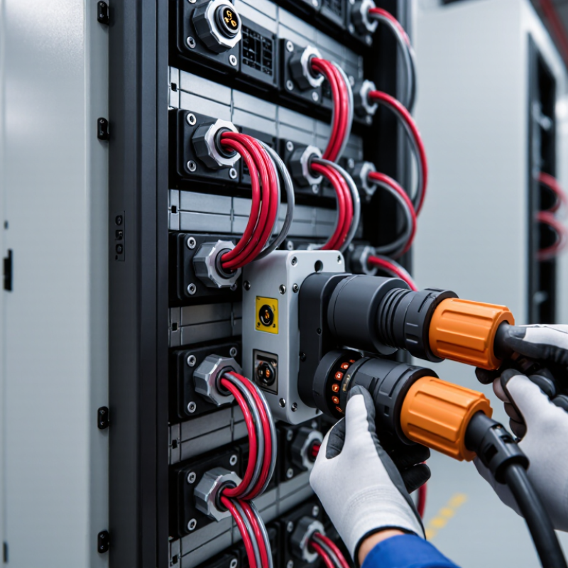
| Typical ESS Location | - Battery module terminals
- Rack busbars and power distribution units
- Permanent internal connections
| - Battery racks and cabinet interfaces
- Service disconnects
- Portable or replaceable battery assemblies
| - Modular battery packs
- Rack-to-rack power links
- Field-installable DC distribution
| - Battery-management systems
- Temperature and voltage sensing
- Contactor, interlock, and communication circuits
| - Battery modules mounted directly to a busbar
- Compact power-electronics assemblies
- Low-inductance internal current paths
|
| Typical Current Capability | 50–1,000 A
Depends on conductor cross-section, temperature rise, bolt preload, and busbar design. | 100–600 A
Higher-current versions exist, but continuous current is strongly affected by cable size and cooling. | 20–350 A
Suitable for modular power paths where touch protection and fast installation are priorities. | 0.1–20 A
Power contacts may be rated higher, but signal contacts are normally selected for low-current circuits. | 50–1,500 A
Current is governed mainly by busbar thickness, joint area, thermal path, and allowable temperature rise. |
| Common DC Voltage Range | Up to 1,500 V DC
Insulation, creepage, clearance, and working-voltage requirements must be checked for the complete assembly. | Up to 1,500 V DC
Touch-safe shrouds, keyed housings, and an appropriate DC rating are essential. | Up to 1,500 V DC
Often used in high-voltage battery systems when finger protection and polarization are required. | Typically below 60 V DC
Higher-voltage auxiliary connectors require additional insulation and touch-protection measures. | Up to 1,500 V DC
Voltage capability depends on spacing, encapsulation, insulation system, and environmental conditions. |
| Contact Design | - Flat copper or copper-alloy lug
- Bolted clamped joint
- Optional plated contact interface
| - Spring-finger, lamella, or multi-point socket contact
- Positive locking mechanism
- Optional auxiliary or pilot contacts
| - Stamped-and-formed or machined socket contact
- Contact springs maintain normal force
- Keyed and touch-safe mating interface
| - Stamped spring contacts or machined pins
- Multiple contact sizes in one housing
- Shielded pairs may be used for data circuits
| - Direct pressure contact or bolted interface
- Stamped copper spring fingers may accommodate tolerance
- Short current path and low loop inductance
|
| Preferred Contact Materials | - Electrolytic copper for high conductivity
- Copper alloy where greater mechanical strength is needed
- Tin or silver plating selected for the environment and current level
| - Copper alloy spring contact
- Silver plating for high-current or high-temperature applications
- Tin plating for many general-purpose copper interfaces
| - Copper alloy contact system
- Tin plating for cost-effective power connections
- Silver plating for demanding current and temperature conditions
| - Copper alloy contacts
- Gold plating for low-level signals and repeated mating
- Tin plating for many power and low-cost control circuits
| - High-conductivity copper or copper alloy
- Tin, nickel, or silver surface finish depending on temperature and corrosion requirements
- Surface flatness is critical for low resistance
|
| Housing and Insulation Materials | - Glass-filled thermoplastic insulating supports
- Thermoset insulating parts in high-temperature designs
- Metal hardware normally isolated from live conductors
| - Flame-retardant polyamide or other high-temperature thermoplastic
- Elastomer seals for environmental protection
- Optional shielding or strain-relief components
| - Flame-retardant, glass-filled polyamide or equivalent thermoplastic
- Silicone or elastomer sealing elements
- Color and keying used to prevent incorrect mating
| - Flame-retardant thermoplastic housing
- Elastomer gaskets for sealed applications
- Shielding shell may be nickel-plated copper alloy or conductive composite
| - Polyester, polyamide, or other electrical insulation system
- Insulating films and molded barriers
- Encapsulation may be used to improve vibration and contamination resistance
|
| Serviceability and Mating Frequency | - Best for permanent or infrequently serviced joints
- Requires controlled torque and inspection
- Not intended for frequent hot-plugging
| - Designed for repeated service access
- Typical mechanical endurance: approximately 50–500 cycles, depending on design
- Must not be disconnected under load unless specifically rated
| - Suitable for modular service and replacement
- Typical mechanical endurance: approximately 50–1,000 cycles
- Interlock or pre-charge functions may be integrated
| - Designed for repeated low-current mating
- Typical mechanical endurance: approximately 50–5,000 cycles
- Contact wiping action helps maintain signal reliability
| - Generally intended for assembly rather than routine service
- Repeated removal can damage plating or reduce contact force
- Fasteners and alignment features require controlled installation
|
| Environmental Protection | - Protection is provided by enclosure, covers, and barriers
- Open joints require protection from dust, moisture, and accidental contact
- Corrosion control is important in humid environments
| - Sealed versions commonly target IP65–IP69K when fully mated
- Requires correct cable seal and backshell installation
- Ingress rating may decrease when unmated
| - Commonly available with IP54–IP68 protection when mated
- Touch-safe construction reduces accidental contact risk
- Seal compression must be maintained during service
| - Unsealed board-level types may have no IP rating
- Sealed cable types commonly provide IP65–IP68 when mated
- Shield termination must be compatible with the enclosure strategy
| - Usually protected by the battery module or enclosure
- Additional sealing or conformal protection may be needed
- Contamination control is important at the contact interface
|
| Main Advantages | - Low contact resistance
- High current capability
- Compact and economical for permanent joints
- Simple visual inspection
| - Fast field connection and disconnection
- Good serviceability
- Can combine power, pilot, and interlock circuits
- Reduced wiring error with keying
| - Touch-safe and polarized
- Modular installation
- Supports high-voltage battery architectures
- Can be integrated with pre-charge or interlock functions
| - Efficient monitoring and control integration
- High contact density
- Suitable for sensors and digital communication
- Shielding options support electromagnetic compatibility
| - Very short and low-inductance current path
- Compact packaging
- Low electrical resistance when properly assembled
- Suitable for high-power internal connections
|
| Main Limitations | - Requires accurate torque control
- Limited service convenience
- Loose hardware can create localized heating
- Open live parts need robust barriers
| - Higher cost than simple bolted joints
- Contact wear and contamination must be managed
- Improper mating can cause overheating
- Not automatically safe for energized disconnection
| - More complex housing and locking system
- Higher insertion force at large contact sizes
- Current derating may be required in tightly packed assemblies
- Must verify creepage and clearance for system voltage
| - Not intended to carry main battery current
- Signal integrity can be affected by noise and shielding errors
- Small contacts are sensitive to damage and contamination
- Pin assignment must be controlled carefully
| - Requires precise alignment and flatness
- Usually not suitable for frequent field disconnection
- Thermal expansion can affect contact pressure
- Manufacturing tolerances must be tightly controlled
|
| Best Fit for 2026 ESS Designs | - High-current internal paths
- Fixed battery-module connections
- Applications prioritizing low cost and low resistance
| - Serviceable battery racks
- Containerized storage systems
- Installations requiring frequent module replacement
| - High-voltage modular racks
- Systems requiring touch-safe maintenance
- Field assembly with reduced wiring complexity
| - Battery-management and supervisory-control networks
- Temperature, voltage, and current sensing
- Contactor control and safety interlock circuits
| - High-density battery modules
- Power-electronics assemblies with strict space limits
- Designs requiring minimized parasitic inductance
|
| Key Verification Items Before Approval | - Continuous and peak current
- Torque, joint resistance, and temperature rise
- Short-circuit withstand capability
- Creepage, clearance, and touch protection
| - Rated voltage and current under actual cable size
- Contact resistance and temperature rise
- Locking, CPA, and HVIL functions
- Vibration, shock, and ingress performance
| - Finger-safe construction
- Keying and polarization
- Derating curve at the intended ambient temperature
- Insertion force and service-cycle life
| - Signal bandwidth and contact resistance
- EMC and shielding performance
- Pin retention and miswiring prevention
- Insulation resistance and environmental sealing
| - Busbar flatness and alignment tolerance
- Contact pressure over temperature and vibration
- Joint resistance and thermal distribution
- Insulation barriers and manufacturing repeatability
|